
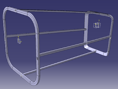
For the purposes of this post and all future posts, each part is numbered between 1 and 4, where 1 is the most left-hand part and 4 is the most right-hand. The first component I completed was part 3, since it was the simplest to design and gave me some more practice creating such interior structures. Here it is with the skin:


And without:
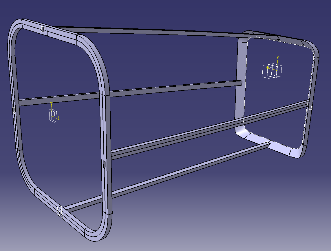
There are four ribs that run across the interior of the component, which provide stability for an otherwise-thin shell. I initially placed these ribs on the corners of the skin, but after printing I found that the part was still very wobbly. The above design was much sturdier. Also, as with the wings from before, I left 0.5mm of space between the ribs and skin to account for the plastic's thickness while printing:


In addition, I added male and female parts on the faces of the perimeter ribs to allow for a stronger connection once I glue the whole airplane together. Each hole is 2mm x 3mm, and the male parts are 1mm x 2mm:


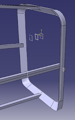
The last important aspect of this part is the back rib, which I had to make slanted in order to allow the printer to create a base for the rib from which the component could be printed:

Next up I'll show part 4 of the airplane, which contains the horizontal and vertical stabilizers:


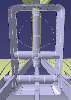
First up I'll show more detailed pictures of the fuselage, which includes all the ribs and rods which will be used to turn the ailerons of the plane. The fuselage and stabilizers will be printed separately, but the body of the plane will include part of the stabilizer since they are angled relative to the body. By doing this the mechanisms for spinning the ailerons will be simplified, and printing the components will be much easier. Here is a picture of how the fuselage will be printed later on:


Note how the horizontal stabilizer's shell, for example, is included with the rest of the fuselage, and how the base of the stabilizer is parallel to the yz plane. Here is the same image without the fuselage skin:


There are female holes in the front rib to allow a better connection with part 3, as seen earlier. Now I'll zoom in on the rods that will spin the different stabilizers:
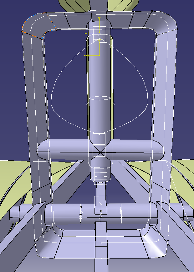
Also note that this second rib is similarly built to the one in part 3 to allow the printer to create the part successfully. It is also much thicker to provide better support for the entire structure:


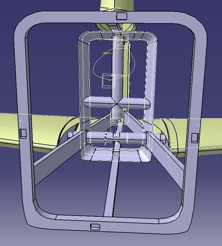
Now let us look at the horizontal stabilizer rods first:


The rods in red are the pieces that will be spinning the stabilizers, but will be made out of metal I will purchase later. The tube in yellow is hollow, and will serve as a stabilizing component to the spinning rods. Finally, the hole in that tube, shown in green, will make way for the servos to be connected to the rods via wiring. This design won't allow for the independent rotation of each horizontal stabilizer, but it should suffice for my purposes. I also used a similar design for the vertical stabilizer (a tube surrounding the spinning rod for stabilization), but also includes another perpendicular rod where the rest of the cylinders will be sturdily mounted. There is also a hole on the bottom where the spinning rod will puncture through and be attached to another servo in the future:


Finally, I will show how I built the interior structure of the stabilizers. This part of the process was fairly simple, since it just involved creating a base "plate" for each wing and a supporting rib that would run through its entirety:


I decided not to create a lattice support structure, like with the wings, because the stabilizers are significantly smaller than the wings, and thus are not long enough to require stronger stabilization to resist torque or its own weight. I might have to revise this once I actually begin printing, but for now it will suffice.
No comments:
Post a Comment