The tunnel measures approximately 112 cm long, with the forward diffuse cone section being 30 cm tall and 40 cm wide, and the test section being 16 cm tall and 26 cm wide. The two fans are attached on the right-hand side, and their current supply is varied by the nearby anemometer attached on the side. In addition, there is a clear sliding door in front of the airfoil seen in the picture, along with a clear overhead section to see provide a better view during testing.
Here are the fans along with a top and side view of the testing chambers. I got these from Fry's, and each one is rated to move 103 cubic feet per minute, or around 0.05 cubic meters per second. The airfoil pictured is a 0.1 m by 0.1 m NACA 2412 airfoil, which I 3D printed. It is held upright by four metal rods, which can be placed on a scale to measure the lift when the fans are running. In addition, I added a protractor to allow for more accurate variations of the angle of attack.
Here are some photos of the diffusers. The first one on top is directly in front of the fans, while the other two are at the entrance of the wind tunnel. The purpose of these tubes is to laminate the incoming flow (reduce turbulence by straightening the air) so as to provide a more aesthetically-pleasing airflow along with more accurate lift measurements while testing.
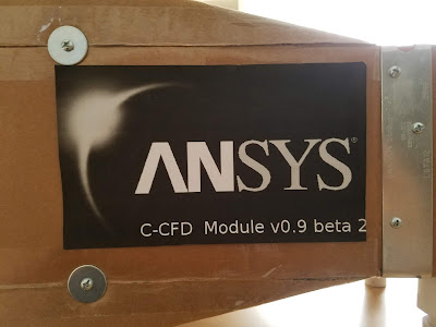
The precursor to ANSYS...:)
Finally, here's the anemometer and electrical setup underneath the wind tunnel. I bought the anemometer online which was built specifically for adjusting fan speeds, so that made the hookup process much easier. Next up, here's a video of water vapor coming from a humidifier flowing over the airfoil. Unfortunately, my humidifier is not very strong, and as a result is a bit hard too see clearly, but hopefully you find the demonstration a little interesting:
And finally, I performed a quick experiment where I measured the lift generated at different angles of attack at the highest possible speed (around 6 m/s), calculated the lift coefficients, and plotted them:
Compare this to actual data for the NACA 2412 airfoil from this website:Although my collected data was all over the place (probably due to my poor scale and slow speed within the wind tunnel), the general trend is still quite similar to the actual measurements for this airfoil. In both instances increasing the angle of attack led to higher lift coefficients at a decreasing rate of change, up until they stalled out at a certain angle (around 30 degrees for my wing). Further increasing alpha simply resulted in lower generated lift until it becomes too high to lift the wing at all.
All in all, I had quite a lot of fun making this wind tunnel, but now I will refocus my efforts on finishing my airplane. I've made a lot of progress in designing the interior structure of the plane along with figuring out how all the electronic components will eventually fit into the craft as a whole. I'll post another update as soon as I have more information.


No comments:
Post a Comment