Updates
As was promised at the end of the original post, I've made a few updates over the last three days to the program to truly flesh it out and add additional functionality. While I won't dive into each update's details since this post is already ridiculously long, I'll just list them and provide a bit of information regarding their implementation:
- Bounding box is now colored white.
- Pressing escape will de-select all vertices.
- Pressing 'r' will reset the entire mesh.
- Press 'F7' to save the current mesh.
- Mesh data is separated into three different files - one for the vertex positions, another for the line colors, and a third for the point colors. This same polygon will be rendered on-screen the next time the program is run.
- Moving multiple vertices at once is now possible by selecting the desired points and pressing the "Alt" button while holding down the left mouse button and dragging.
- Display/hide a background grid by pressing 'g.' The grid will also resize itself based on the window size.
- Press the up and down arrow keys to increase/decrease the grid density.
- Press 's' to activate/deactivate snap-to-grid functionality. When turned on, all translated/added points will be discretely altered along the grid (which automatically shows up if snap-to-grid is on).
- Pressing the middle mouse button will activate a function that determines whether the mouse cursor position is contained within the mesh; the result is printed to the console. Check out this website for the implementation specifics.
Here's a little video to demonstrate some of this functionality:
The below links to the actual project have also been updated with the current version. Also note that the original post's code/explanations remains relevant, and has not been rendered obsolete by the above changes.
______________________________________________________________________________
2D Shape Modeler
As I mentioned towards the end of a
previous blog post, one of the projects I wanted to undertake was to simulate the airflow inside a
scramjet where the user could directly modify the engine's geometry. So, as a jumping-off point I decided to create the following 2D shape-editing tool, which allows one to move, add, and delete a 2-dimensional mesh's vertices to form custom polygons, and whose logic can later be recycled for the scramjet simulation. Here's a little demonstration of what the program is currently capable of:
As can be seen, currently-supported features include selecting/deselecting vertices (both individually with left-mouse clicks and via drag-and-drop), adding and deleting points to and from the mesh, and moving vertices through space. Also note that selected vertices change color from purple to yellow.
While this project is a stepping stone in my effort to simulate scramjet airflow, it also served as valuable practice in designing and managing clean code with a well-defined architecture, as small and simple as it is, while also serving as a benign introduction to the messiness behind poly-modeling. To that end, special emphasis will be put on highlighting how I maintained some semblance of structure along with the unique challenges shape modification brought with it.
Vertex and Fragment Shaders
First up we'll define the vertex and fragment shaders. For this project the shaders were very simple, and were stored as .txt files:
//vertex shader
#version 400
layout(location = 0) in vec2 vertex;
layout(location = 1) in vec3 inColor;
out vec3 color;
uniform mat4 projection;
void main()
{
gl_Position = projection * vec4(vertex.xy, 0.0f, 1.0f);
gl_PointSize = 4.0f;
color = inColor;
}
---------------------------------------------
//fragment shader
#version 400
in vec3 color;
out vec4 outColor;
void main()
{
outColor = vec4(color, 1.0f);
}
Here the vertex shader transforms the inputted vertex positions to screen space, scales the point sizes up to increase visibility, and spits the given color out to the fragment shader for processing. One interesting thing to note is the lack of a model matrix whilst transforming the vertices. This is because the projection matrix has been defined to set the world-space coordinates to screen space positions, effectively reducing the number of transformations one needs to go through. In other words, the local space coordinates are being projected so that their world-space positions are equal to the screen space ones as well, which is quite intuitive for this 2D application.
Now let's get to the interesting part - how the actual modeling is accounted for.
Model - Math/Data Handler
model.h
The following header file includes not only a Model class to house all the necessary functions, but a ModelData struct where all the flags, vertices, selected vertex indices, and other data relevant to the modeling process are found. I decided to store this data within a struct because a) I wanted to separate the simpler, yet somewhat more expansive, variables from the more complex functions, and b) they would, by default, have public visibility, thus allowing me to more easily set/call upon the stored variables across the entire project. The actual ModelData struct is presented here:
struct ModelData
{
std::vector<GLboolean> VertexSelected;
std::vector<GLfloat> Vertices, PointVertices, LineColors, PointColors;
GLboolean AddShape, Delete;
GLboolean LeftMouseButtonPressed, LeftMouseButtonDown, LeftMouseButtonUp;
GLboolean ShiftLeftMouseButtonPressed, ShiftLeftMouseButtonDown, ShiftLeftMouseButtonUp;
GLboolean CtrlLeftMouseButtonPressed, CtrlLeftMouseButtonDown, CtrlLeftMouseButtonUp;
GLboolean RightMouseButtonPressed, RightMouseButtonDown, RightMouseButtonUp;
GLboolean BufferSelectVertices, BufferMoveVertex, BufferAddVertices, BufferAddShape, BufferDeleteVertices, BoundingBoxAdd, BoundingBoxDelete;
GLint WindowWidth = 500, WindowHeight = 500;
};
A few clarifications. One, there are two separate variables storing the vertex positions -
Vertices and PointVertices. The former is used in drawing the (blue) line and bounding box, while the latter is utilized in rendering the purple points as seen in the video. Data-wise both are almost identical (except when a bounding box is drawn, in which case PointVertices isn't altered at all). Two, the VertexSelected vector holds a boolean for every vertex to store its selection status, and three, the long list of buffer booleans towards the end will eventually be used to only update the VBOs if the user has interacted with/altered the mesh (more on that later).
The corresponding Model class is as shown:
class Model
{
public:
Model();
~Model();
void SelectVertex(glm::vec2 &initialLeftMousePosition, glm::vec2 &leftMousePosition);
void AddToSelectedVertices(glm::vec2 &initialLeftMousePosition, glm::vec2 &leftMousePosition);
void RemoveSelectedVertices(glm::vec2 &initialLeftMousePosition, glm::vec2 &leftMousePosition);
void MoveVertex(glm::vec2 &leftMousePosition);
void AddVertices(glm::vec2 &initialRightMousePosition);
void AddShape();
void DeleteVertices();
void PointColor();
private:
void initModelData();
void closestLine(glm::vec2 &initialRightMousePosition);
void instantiateBoundingBox(glm::vec2 &initialLeftMousePosition, glm::vec2 &leftMousePosition);
void destroyBoundingBox();
};
extern ModelData modelData;
extern Model model;
Note that we also define two externs, one for
Model and the other for ModelData, so that we can call upon the functions and data defined here anywhere else in the project.
model.cpp
Initializing the Data
Before jumping into the nitty-gritty code behind 2D poly-editing, we need to initialize a few parameters. First we define the following global variables/arrays:
ModelData modelData;
Model model;
GLfloat vertices[] =
{
150.0f, 150.0f, //line 0
150.0f, 350.0f,
150.0f, 350.0f, //line 1
350.0f, 350.0f,
350.0f, 350.0f, //line 2
350.0f, 150.0f,
350.0f, 150.0f, //line 3
150.0f, 150.0f
};
GLfloat newVertices[] =
{
200.0f, 200.0f, //line 0
200.0f, 300.0f,
200.0f, 300.0f, //line 1
300.0f, 300.0f,
300.0f, 300.0f, //line 2
300.0f, 200.0f,
300.0f, 200.0f, //line 3
200.0f, 200.0f
};
GLfloat lineColors[] =
{
0.0f, 1.0f, 1.0f,
0.0f, 1.0f, 1.0f,
0.0f, 1.0f, 1.0f,
0.0f, 1.0f, 1.0f,
0.0f, 1.0f, 1.0f,
0.0f, 1.0f, 1.0f,
0.0f, 1.0f, 1.0f,
0.0f, 1.0f, 1.0f
};
GLfloat pointColors[] =
{
1.0f, 0.25f, 0.75f, //line 0
1.0f, 0.25f, 0.75f,
1.0f, 0.25f, 0.75f, //line 1
1.0f, 0.25f, 0.75f,
1.0f, 0.25f, 0.75f, //line 2
1.0f, 0.25f, 0.75f,
1.0f, 0.25f, 0.75f, //line 3
1.0f, 0.25f, 0.75f
};
GLfloat minimumDistance = 1000.0f;
GLint closestVector;
GLboolean selectMultipleVertices = GL_FALSE;
std::vector<GLint> vertexID;
The arrays are pretty self-explanatory.
vertices stores the initial vertex coordinates, lineColors the colors of the lines, and pointColors the colors of the points. A bit less clear, newVertices houses the vertex positions for the new square that is created every time the space bar is pressed, and
vertexID holds the IDs of the two paired vertices every time a single point is selected.
One design choice I would like to discuss here is why I didn't use an element buffer object to index my vertices and prevent overlap within the mesh, since the above code ends up creating two separate points for a given position. While optimizing the program in such a way does seem attractive, and is something I initially tried implementing, ultimately I found that attempting to correctly track every single vertex became extremely difficult, especially when a user began adding or deleting vertices. So, I decided to trade those potential optimizations for simplicity, since with the above method every pair of vertices (i.e. every 4 values) becomes a self-contained line that doesn't care about its position within the Vertices vector, thereby disentangling the addition and deletion process, as will be discussed later. This might be something I revisit sometime soon in the future, but for now it gets the job done.
Using the above arrays, we can now push back on their respective vector forms to initialize those data containers:
void Model::initModelData()
{
for (int i = 0; i < sizeof(vertices) / sizeof(*vertices); ++i)
{
modelData.Vertices.push_back(vertices[i]);
modelData.PointVertices.push_back(vertices[i]);
}
for (int i = 0; i < 0.5f * modelData.Vertices.size(); ++i) modelData.VertexSelected.push_back(GL_FALSE);
vertexID.push_back(-1);
vertexID.push_back(-1);
for (int i = 0; i < sizeof(lineColors) / sizeof(*lineColors); ++i) modelData.LineColors.push_back(lineColors[i]);
for (int i = 0; i < sizeof(pointColors) / sizeof(*pointColors); ++i) modelData.PointColors.push_back(pointColors[i]);
}
Before calling the private method in the
Model constructor:
Model::Model()
{
this->initModelData();
}
Now that all of the data is accounted for, we can begin interacting with the model in meaningful ways. We will first discuss the creation of the bounding box whenever the mouse is dragged along the screen
Creating/Destroying the Bounding Box
The bounding box logic is separated into two private functions - instantiateBoundingBox() and destroyBoundingBox(). The first method initializes the box when the user presses the left mouse button and is not selecting a single vertex (i.e. the two positions do not match up) and allows them to alter its size by moving the mouse, while the second deletes the box once the left mouse button is released.
instantiateBoundingBox() is presented here in full:
void Model::instantiateBoundingBox(glm::vec2 &initialLeftMousePosition, glm::vec2 &leftMousePosition)
{
if (selectMultipleVertices)
{
modelData.Vertices[modelData.Vertices.size() - 16 + 3] = leftMousePosition.y;
modelData.Vertices[modelData.Vertices.size() - 16 + 5] = leftMousePosition.y;
modelData.Vertices[modelData.Vertices.size() - 16 + 6] = leftMousePosition.x;
modelData.Vertices[modelData.Vertices.size() - 16 + 7] = leftMousePosition.y;
modelData.Vertices[modelData.Vertices.size() - 16 + 8] = leftMousePosition.x;
modelData.Vertices[modelData.Vertices.size() - 16 + 9] = leftMousePosition.y;
modelData.Vertices[modelData.Vertices.size() - 16 + 10] = leftMousePosition.x;
modelData.Vertices[modelData.Vertices.size() - 16 + 12] = leftMousePosition.x;
modelData.BufferSelectVertices = GL_TRUE;
}
else if (!selectMultipleVertices)
{
selectMultipleVertices = GL_TRUE;
for (int i = 0; i < 8; ++i)
{
modelData.Vertices.push_back(initialLeftMousePosition.x);
modelData.Vertices.push_back(initialLeftMousePosition.y);
}
for (int i = 0; i < 8; ++i)
{
modelData.LineColors.push_back(0.0f);
modelData.LineColors.push_back(1.0f);
modelData.LineColors.push_back(1.0f);
modelData.PointColors.push_back(0.0f);
modelData.PointColors.push_back(1.0f);
modelData.PointColors.push_back(1.0f);
 }
}
modelData.BufferSelectVertices = GL_TRUE;
}
Let's break this down a little further. First note the
selectMultipleVertices flag which, by default, is set to false. What this value does is differentiate between whether the function should instantiate the bounding box by pushing back four vertex values and the corresponding colors (all equal to the initial mouse position), or altering said vertex positions based on the current mouse position. This also ensures that a new box isn't continuously
created whenever the button is held down.
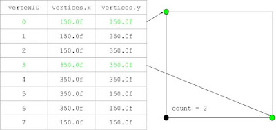
As was stated earlier, the user can change the box's size by holding the left mouse button down and moving the mouse. This is done by modifying certain box vertices to replicate the usual drag-and-drop mechanic. A simple diagram can help explain:
Basically, the box's vertex elements are changed in such a manner as to create a box whenever the mouse is dragged; one of the vertices will equal the initial mouse position, another the current mouse position, and the last two will be dependent on either the current x or y cursor positions. Note that this process needs to be done twice since every position on-screen has two corresponding vertices. Lastly, the
BufferSelectVertices boolean is set to true, and tells the sprite renderer to update the VBOs before redrawing the object (more on that later).
Now that this rectangle has been created, we need to destroy it once the button is released:
void Model::destroyBoundingBox()
{
selectMultipleVertices = GL_FALSE;
GLfloat xMax = -1.0f, xMin = 1000.0f, yMax = -1.0f, yMin = 1000.0f;
for (int i = (int)(0.5f * (modelData.Vertices.size() - 16)); i < (int)(0.5f * modelData.Vertices.size()); ++i)
{
if (modelData.Vertices[2 * i] > xMax) xMax = modelData.Vertices[2 * i];
if (modelData.Vertices[2 * i] < xMin) xMin = modelData.Vertices[2 * i];
if (modelData.Vertices[2 * i + 1] > yMax) yMax = modelData.Vertices[2 * i + 1];
if (modelData.Vertices[2 * i + 1] < yMin) yMin = modelData.Vertices[2 * i + 1];
}
for (int i = 0; i < (int)(0.5f * (modelData.Vertices.size() - 16)); ++i)
{
if (modelData.Vertices[2 * i] >= xMin && modelData.Vertices[2 * i] <= xMax && modelData.Vertices[2 * i + 1] >= yMin && modelData.Vertices[2 * i + 1] <= yMax)
{
if (modelData.BoundingBoxAdd) modelData.VertexSelected[i] = GL_TRUE;
else if (modelData.BoundingBoxDelete) modelData.VertexSelected[i] = GL_FALSE;
}
}
for (int i = 0; i < 16; ++i) modelData.Vertices.erase(modelData.Vertices.begin() + modelData.Vertices.size() - 1);
for (int i = 0; i < 24; ++i)
{
modelData.LineColors.erase(modelData.LineColors.begin() + modelData.LineColors.size() - 1);
modelData.PointColors.erase(modelData.PointColors.begin() + modelData.PointColors.size() - 1);
}
modelData.BufferSelectVertices = GL_TRUE;
}
A few things are happening here. Before we actually delete the box by erasing the last 16 elements off
Vertices and the corresponding colors, we need to find what range (in both the x- and y- directions) the box encompassed when the mouse button was held up. Using these values we can then loop over the Vertices vector to determine if any of the vertices fall within that range, which comes in handy for selecting/deselecting vertices from our VertexSelected() vector. BufferSelectVertices also gets turned off to prevent useless updates to the VBO since the data isn't currently being changed. This type of flag is used throughout the project for every single function that directly alters the vertex elements, thereby significantly reducing overhead.
With the data initialized and the bounding box logic ready to go, we can now begin talking about the more interesting Model functions. First on the list is selecting vertices.
Vertex Selection
There are two different cases that need to be handled by this function - selecting a single vertex by directly pressing it, and dragging the bounding box over any number of vertices to select them. The former is handled like so:
void Model::SelectVertex(glm::vec2 &initialLeftMousePosition, glm::vec2 &leftMousePosition)
{
if (modelData.LeftMouseButtonPressed)
{
modelData.ShiftLeftMouseButtonPressed = modelData.ShiftLeftMouseButtonDown = modelData.ShiftLeftMouseButtonUp = GL_FALSE;
modelData.CtrlLeftMouseButtonPressed = modelData.CtrlLeftMouseButtonDown = modelData.CtrlLeftMouseButtonUp = GL_FALSE;
modelData.BoundingBoxAdd = GL_TRUE;
modelData.BoundingBoxDelete = GL_FALSE;
vertexID.clear();
for (int i = 0; i < (int)modelData.VertexSelected.size(); ++i) modelData.VertexSelected[i] = GL_FALSE;
for (int i = 0; i < (int)(0.5f * modelData.Vertices.size()); ++i)
{
if (leftMousePosition.x >= modelData.Vertices[2 * i] - 10 && leftMousePosition.x <= modelData.Vertices[2 * i] + 10 && leftMousePosition.y >= modelData.Vertices[2 * i + 1] - 10 && leftMousePosition.y <= modelData.Vertices[2 * i + 1] + 10)
{
modelData.VertexSelected[i] = GL_TRUE;
modelData.BoundingBoxAdd = GL_FALSE;
vertexID.push_back(i);
}
}
modelData.LeftMouseButtonPressed = GL_FALSE;
modelData.LeftMouseButtonDown = GL_TRUE;
modelData.BufferSelectVertices = GL_TRUE;
}
...
}
The second for-loop is the important one. All we're doing is looping through the vertices and checking if any of their positions (within a given tolerance) correspond to the mouse's position when the left button was pressed. If this is true, then the corresponding boolean in
VertexSelected becomes activated as well.
Some other processes that are being taken care of here, include deactivating any special left mouse button clicks (which will be used shortly), clearing and setting the vertexID vector (which stores the single vertex locations within Vertices whenever one is clicked on), and switching the left mouse button state from "pressed" to "down" (connoting that the button is being held down over time). In addition to this, the BoundingBoxAdd flag is turned on to let destoryBoundingBox() know that any vertices that fall within its capture range should be added to the list of selected points:
void Model::SelectVertex(glm::vec2 &initialLeftMousePosition, glm::vec2 &leftMousePosition)
{
...
else if (modelData.LeftMouseButtonDown && modelData.BoundingBoxAdd)
{
model.instantiateBoundingBox(initialLeftMousePosition, leftMousePosition);
}
else if (modelData.LeftMouseButtonUp && modelData.BoundingBoxAdd)
{
model.destroyBoundingBox();
modelData.LeftMouseButtonUp = GL_FALSE;
}
else modelData.BufferSelectVertices = GL_FALSE;
}
While this function allows one to select any number of vertices, it does not support any sort of adjustment methods to select even further (or deselect any) points. If one ran this code and tried clicking on multiple vertices in the hopes of selecting all of them, for example, the former selected vertex would be deselected while the newly-clicked one would have its selection status set to true, an effect achieved by this one line of code:
for (int i = 0; i < (int)modelData.VertexSelected.size(); ++i) modelData.VertexSelected[i] = GL_FALSE;
Which sets all
VertexSelected elements as being false. The addition and subtraction of selected vertices is thus handled by the following methods.
Adding/Deleting Vertices to the Selection List
Adding vertices to the collection of already-selected points is quite straightforward. In fact, the method is almost exactly the same as the above one:
void Model::AddToSelectedVertices(glm::vec2 &initialLeftMousePosition, glm::vec2 &leftMousePosition)
{
if (modelData.ShiftLeftMouseButtonPressed)
{
modelData.LeftMouseButtonPressed = modelData.LeftMouseButtonDown = modelData.LeftMouseButtonUp = GL_FALSE;
modelData.CtrlLeftMouseButtonPressed = modelData.CtrlLeftMouseButtonDown = modelData.CtrlLeftMouseButtonUp = GL_FALSE;
modelData.BoundingBoxAdd = GL_TRUE;
modelData.BoundingBoxDelete = GL_FALSE;
for (int i = 0; i < (int)(0.5f * modelData.Vertices.size()); ++i)
{
if (leftMousePosition.x >= modelData.Vertices[2 * i] - 10 && leftMousePosition.x <= modelData.Vertices[2 * i] + 10 && leftMousePosition.y >= modelData.Vertices[2 * i + 1] - 10 && leftMousePosition.y <= modelData.Vertices[2 * i + 1] + 10)
{
modelData.VertexSelected[i] = GL_TRUE;
modelData.BoundingBoxAdd = GL_FALSE;
}
}
modelData.ShiftLeftMouseButtonPressed = GL_FALSE;
modelData.ShiftLeftMouseButtonDown = GL_TRUE;
modelData.BufferSelectVertices = GL_TRUE;
}
else if (modelData.ShiftLeftMouseButtonDown && modelData.BoundingBoxAdd)
{
model.instantiateBoundingBox(initialLeftMousePosition, leftMousePosition);
}
else if (modelData.ShiftLeftMouseButtonUp && modelData.BoundingBoxAdd)
{
model.destroyBoundingBox();
modelData.ShiftLeftMouseButtonUp = GL_FALSE;
}
}
The only major differences between the two are that:
- AddToSelectedVertices() gets called when the left mouse button AND shift are held down at the same time.
- The vertex selection status isn't reset every time the function is called.
Apart from that, this method allows one to add selected vertices by holding down shift and either clicking on vertices one-by-one, or dragging-and-dropping over whatever points one desires.
Likewise, removing selected vertices is an extremely similar piece of code:
void Model::RemoveSelectedVertices(glm::vec2 &initialLeftMousePosition, glm::vec2 &leftMousePosition)
{
if (modelData.CtrlLeftMouseButtonPressed)
{
modelData.LeftMouseButtonPressed = modelData.LeftMouseButtonDown = modelData.LeftMouseButtonUp = GL_FALSE;
modelData.ShiftLeftMouseButtonPressed = modelData.ShiftLeftMouseButtonDown = modelData.ShiftLeftMouseButtonUp = GL_FALSE;
modelData.BoundingBoxAdd = GL_FALSE;
modelData.BoundingBoxDelete = GL_TRUE;
for (int i = 0; i < (int)(0.5f * modelData.Vertices.size()); ++i)
{
if (leftMousePosition.x >= modelData.Vertices[2 * i] - 10 && leftMousePosition.x <= modelData.Vertices[2 * i] + 10 && leftMousePosition.y >= modelData.Vertices[2 * i + 1] - 10 && leftMousePosition.y <= modelData.Vertices[2 * i + 1] + 10)
{
modelData.VertexSelected[i] = GL_FALSE;
modelData.BoundingBoxDelete = GL_FALSE;
}
}
modelData.CtrlLeftMouseButtonPressed = GL_FALSE;
modelData.CtrlLeftMouseButtonDown = GL_TRUE;
modelData.BufferSelectVertices = GL_TRUE;
}
else if (modelData.CtrlLeftMouseButtonDown && modelData.BoundingBoxDelete)
{
model.instantiateBoundingBox(initialLeftMousePosition, leftMousePosition);
}
else if (modelData.CtrlLeftMouseButtonUp && modelData.BoundingBoxDelete)
{
model.destroyBoundingBox();
modelData.CtrlLeftMouseButtonUp = GL_FALSE;
}
}
Which gets called when Ctrl is pressed with the left mouse button, and instead sets
BoundingBoxDelete as true so that selected vertices actually get turned off in VertexSelected.
With vertex selection set up, it's now time to discuss moving a point with the mouse cursor.
Moving A Vertex
As of right now, this project only supports the user moving one vertex at a time, something I hope to update in the coming days. As for how the actual feature works, all it does is use the selected vertex positions within Vertices, which was stored within vertexID after a single point was clicked on, and reset those vertex positions in world/screen space to the mouse's coordinates. Here is what it looks like:
void Model::MoveVertex(glm::vec2 &leftMousePosition)
{
if (modelData.LeftMouseButtonDown)
{
if (modelData.VertexSelected[vertexID[0]] == GL_TRUE || modelData.VertexSelected[vertexID[1]] == GL_TRUE)
{
modelData.Vertices[2 * vertexID[0]] = leftMousePosition.x;
modelData.Vertices[2 * vertexID[1]] = leftMousePosition.x;
modelData.Vertices[2 * vertexID[0] + 1] = leftMousePosition.y;
modelData.Vertices[2 * vertexID[1] + 1] = leftMousePosition.y;
modelData.PointVertices[2 * vertexID[0]] = leftMousePosition.x;
modelData.PointVertices[2 * vertexID[1]] = leftMousePosition.x;
modelData.PointVertices[2 * vertexID[0] + 1] = leftMousePosition.y;
modelData.PointVertices[2 * vertexID[1] + 1] = leftMousePosition.y;
modelData.BufferMoveVertex = GL_TRUE;
}
}
else modelData.BufferMoveVertex = GL_FALSE;
}
Note that this substitution is also performed on
PointVertices, since it is responsible for storing the data that is ultimately used to render the purple dots on-screen.
While the functions described thus far do provide some interactivity with the starting mesh, there's still no way to change the polygon's structure other than moving some points around. A solid next step would be to include a method to add vertices to the mesh, allowing one to create all sorts of crazy shapes.
Adding Vertices to the Mesh - Closest Line
In this project one can add vertices to the mesh object at the current mouse position every time the right button is pressed. If we look at the function, however, a call is made to the private method closestLine() before the vertex data is manipulated in any fashion:
void Model::AddVertices(glm::vec2 &initialRightMousePosition)
{
if (modelData.RightMouseButtonPressed)
{
this->closestLine(initialRightMousePosition);
...
}
else modelData.BufferAddVertices = GL_FALSE;
}
closestLine() determines which line is closest to the specified position, and returns the relevant line index that allows for later altering of the local connectivity. Let's take a look at this method and see how it works its magic:
void Model::closestLine(glm::vec2 &initialRightMousePosition)
{
for (int i = 0; i < (int)(0.25f * modelData.Vertices.size()); ++i)
{
glm::vec2 polygonVectors = glm::vec2(modelData.Vertices[4 * i + 2] - modelData.Vertices[4 * i], modelData.Vertices[4 * i + 3] - modelData.Vertices[4 * i + 1]);
glm::vec2 pointVector = initialRightMousePosition - glm::vec2(modelData.Vertices[4 * i], modelData.Vertices[4 * i + 1]);
GLfloat projection = glm::dot(polygonVectors, pointVector) / (glm::length(polygonVectors) * glm::length(polygonVectors));
if (projection < 0) projection = 0;
if (projection > 1) projection = 1;
GLfloat distance = sqrtf(glm::dot(pointVector, pointVector) - glm::dot(projection * polygonVectors, projection * polygonVectors));
if (distance < minimumDistance)
{
minimumDistance = distance;
closestVector = i;
  }
 }
}
Here are the steps, along with a simple square shape case for illustrative purposes:
- Loop through every fourth vertex element and define polygonVectors. The reason we iterate like this is because there are four values necessary to define a line in this context - both the x- and y-coordinates of two of the vertices. We subtract the corresponding x- and y-positions for both points and store those values within polygonVectors, thus forming a vector defining the size/orientation of every mesh's side.
- Create a pointVector, which defines a vector between the mouse position and every other point on the mesh. The reason we need to skip over every other vertex is because this vector will eventually be projected onto the mesh's sides, and thus only requires one connection between the new vertex location (the mouse position) and said side (which can be formed with any one of the line's two vertices).
- Project every pointVector along each corresponding instance of polygonVectors.
- Use Pythagoras's Theorem to calculate the distances between pointVector and polygonVectors.
- Output the index for the shortest-calculated distance to the global variable closestVector.
Adding Vertices to the Mesh
Now that the line closest to the vertex we would like to add to the mesh has been calculated, the vertex data can be altered to produce the correct results. The code looks like this:
void Model::AddVertices(glm::vec2 &initialRightMousePosition)
{
 if (modelData.RightMouseButtonPressed)
 {
this->closestLine(initialRightMousePosition);
modelData.Vertices.push_back(initialRightMousePosition.x);
modelData.Vertices.push_back(initialRightMousePosition.y);
modelData.Vertices.push_back(modelData.Vertices[4 * closestVector + 2]);
modelData.Vertices.push_back(modelData.Vertices[4 * closestVector + 3]);
modelData.Vertices[4 * closestVector + 2] = initialRightMousePosition.x;
modelData.Vertices[4 * closestVector + 3] = initialRightMousePosition.y;
modelData.PointVertices.push_back(initialRightMousePosition.x);
modelData.PointVertices.push_back(initialRightMousePosition.y);
modelData.PointVertices.push_back(modelData.PointVertices[4 * closestVector + 2]);
modelData.PointVertices.push_back(modelData.PointVertices[4 * closestVector + 3]);
modelData.PointVertices[4 * closestVector + 2] = initialRightMousePosition.x;
modelData.PointVertices[4 * closestVector + 3] = initialRightMousePosition.y;
modelData.LineColors.push_back(0.0f);
modelData.LineColors.push_back(1.0f);
modelData.LineColors.push_back(1.0f);
modelData.LineColors.push_back(0.0f);
modelData.LineColors.push_back(1.0f);
modelData.LineColors.push_back(1.0f);
modelData.PointColors.push_back(1.0f);
modelData.PointColors.push_back(0.25f);
modelData.PointColors.push_back(0.75f);
modelData.PointColors.push_back(1.0f);
modelData.PointColors.push_back(0.25f);
modelData.PointColors.push_back(0.75f);
modelData.VertexSelected.push_back(GL_FALSE);
modelData.VertexSelected.push_back(GL_FALSE);
minimumDistance = 1000.0f;
closestVector = -1;
modelData.RightMouseButtonPressed = GL_FALSE;
modelData.RightMouseButtonDown = GL_TRUE;
modelData.BufferAddVertices = GL_TRUE;
 }

 else modelData.BufferAddVertices = GL_FALSE;
}
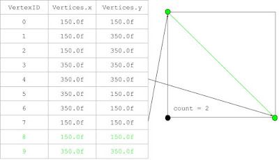
Adding a point to
Vertices boils down to the following few steps (with the same square example to help further demonstrate the process):
- Push back the new vertex's x- and y-positions.
- Push back the closest line's second point onto Vertices. This forms a new line between the added vertex and a copy of the original side's second point.
- Reset the original line's second vertex to the new point's position, thereby terminating the original side and forming two new lines in its place.
- Repeat for PointVertices.
In addition to this we increase the size of VertexSelected and the various coloring vectors to ensure that the newly-added points can be selected/colored correctly, while also resetting the closestVector and minimumDistance values for later calculation.
Add a New Shape
With the ability to add vertices to the original mesh, one now has greater flexibility in the types of shapes that can be designed. However, simply appending vertices using the current method won't allow for a separate mesh object to be instantiated/manipulated; this can be remedied with the following AddShape() method, where the newVertices array will finally become useful:
void Model::AddShape()
{
if (modelData.AddShape)
{
modelData.AddShape = GL_FALSE;
for (int i = 0; i < sizeof(newVertices) / sizeof(*newVertices); ++i)
{
modelData.Vertices.push_back(newVertices[i]);
modelData.PointVertices.push_back(newVertices[i]);
}
for (int i = 0; i < 8; ++i)
{
modelData.VertexSelected.push_back(i);
modelData.LineColors.push_back(0.0f);
modelData.LineColors.push_back(1.0f);
modelData.LineColors.push_back(1.0f);
modelData.PointColors.push_back(1.0f);
modelData.PointColors.push_back(0.25f);
modelData.PointColors.push_back(0.75f);
}
for (int i = (int)modelData.VertexSelected.size() - 8; i < (int)modelData.VertexSelected.size(); ++i)
{
modelData.VertexSelected[i] = GL_FALSE;
}
modelData.BufferAddShape = GL_TRUE;
}
else modelData.BufferAddShape = GL_FALSE;
}
Every time the
AddShape flag is set to true (which only occurs when the space key is pressed), a set of 8 vertices held in newVertices gets pushed back onto Vertices to form a self-contained, albeit smaller, square, that can both be altered using the previously-described functionality and remain independent of any changes made to all other instantiated meshes.
Vertex Deletion
Probably the trickiest method to implement, vertex deletion needs to be handled carefully to ensure that the selected points are deleted correctly while simultaneously ensuring that the connectivity between all other points remains intact. We'll once again break down the process into easier-to-digest chunks and pair it up with a simple deletion example:
- Determine the number of vertices and their positions that have been marked for deletion, and store those values in a temporary count integer and vertexPositions vector:
void Model::DeleteVertices()
{
if (modelData.Delete)
{
GLuint count = 0;
std::vector<GLfloat> vertexPositions;
for (int i = 0; i < (int)(modelData.VertexSelected.size()); ++i)
{
if (modelData.VertexSelected[i] == GL_TRUE)
{
++count;
vertexPositions.push_back(modelData.Vertices[2 * i]);
vertexPositions.push_back(modelData.Vertices[2 * i + 1]);
 }
}
...
}
Note that a vertex will be deleted if it is currently selected and Delete is true (the "delete" button has been clicked). For instance, say we wanted to remove the bottom-left corner from our square; the count and vertex positions would look like this:
- While the count is greater than zero, find the indices of the vertices (i.e. location within Vertices) marked for deletion by comparing their positions in world space to the elements in Vertices:
void Model::DeleteVertices()
{
 if (modelData.Delete)
 {
                while (count > 0)
  {
   GLint index1 = -1, index2 = -1;
   for (int i = 0; i < (int)(0.5f * vertexPositions.size()); ++i)
   {
    for (int j = 0; j < (int)(0.5f * modelData.Vertices.size()); ++j)
    {
     if (modelData.Vertices[2 * j] == vertexPositions[2 * i] && modelData.Vertices[2 * j + 1] == vertexPositions[2 * i + 1] && index1 == -1)
     {
      index1 = j;
     }

     else if (modelData.Vertices[2 * j] == vertexPositions[2 * i] && modelData.Vertices[2 * j + 1] == vertexPositions[2 * i + 1] && index2 == -1)
     {
      index2 = j;
     }

     if (index1 > -1 && index2 > -1) break;
    }
   }
                ...
                }
        ...
        }
}
In the above case the point indices would be 1 and 2. Once these are found, the for-loop is broken and we continue with the function.
- Next calculate the adjacent vertex indices - the points which, when paired with the previous vertices, form line segments.
void Model::DeleteVertices()
{
 if (modelData.Delete)
 {
                while (count > 0)
  {
                ...
                        GLint adjacent1 = -1, adjacent2 = -1;

   if (index1 == 0) adjacent1 = 1;
   else if (index1 == (int)(0.5f * modelData.Vertices.size()) - 1) adjacent1 = (int)(0.5f * modelData.Vertices.size()) - 2;
   else if (index1 % 2 == 1) adjacent1 = index1 - 1;
   else if (index1 % 2 == 0) adjacent1 = index1 + 1;

   if (index2 == 0) adjacent2 = 1;
   else if (index2 == (int)(0.5f * modelData.Vertices.size()) - 1) adjacent2 = (int)(0.5f * modelData.Vertices.size()) - 2;
   else if (index2 % 2 == 1) adjacent2 = index2 - 1;
   else if (index2 % 2 == 0) adjacent2 = index2 + 1;
                ...
                }
        ...
        }
}
Every line that makes up a polygon is formed via even-odd indexed pairs of vertices (i.e. in the example above, vertices 0 and 1 make up the first line, 2 and 3 the second, etc.). This simplifies finding the adjacent points because every odd-indexed vertex will be paired with the smaller even-indexed point next to it, and each even-indexed vertex will create a line with the greater odd vertex it is associated with. For our square example, the adjacent vertices will be:
- As was discussed before, every "point" that is visible on-screen is actually made up of two overlapping vertices, each of which are used to form separate lines. It is with this consideration that we now need to find the overlapping point indices of the adjacent vertices from step 3, which is done by looping through Vertices and comparing each of the element values to those of the adjacent vertices to determine their matching partner:
void Model::DeleteVertices()
{
 if (modelData.Delete)
 {
                while (count > 0)
  {
                ...
                        GLint overlappingAdjacent1 = -1, overlappingAdjacent2 = -1;

   for (int i = 0; i < (int)(0.5f * modelData.Vertices.size()); ++i)
   {
    if (i == adjacent1) continue;
    if (modelData.Vertices[2 * i] == modelData.Vertices[2 * adjacent1] && modelData.Vertices[2 * i + 1] == modelData.Vertices[2 * adjacent1 + 1])
    {
     overlappingAdjacent1 = i;
     break;
    }
   }

   for (int i = 0; i < (int)(0.5f * modelData.Vertices.size()); ++i)
   {
    if (i == adjacent2) continue;
    if (modelData.Vertices[2 * i] == modelData.Vertices[2 * adjacent2] && modelData.Vertices[2 * i + 1] == modelData.Vertices[2 * adjacent2 + 1])
    {
     overlappingAdjacent2 = i;
     break;
    }
   }
                ...
                }
        ...
        }
}
Applied to our case scenario, these overlapping adjacent vertices are:
- Begin geometry reconstruction be adding a line between the overlapping adjacent vertices. This will ensure that the shape remains closed after the selected vertices are deleted:
void Model::DeleteVertices()
{
 if (modelData.Delete)
 {
                while (count > 0)
  {
                ...

   modelData.Vertices.push_back(modelData.Vertices[2 * overlappingAdjacent1]);
   modelData.Vertices.push_back(modelData.Vertices[2 * overlappingAdjacent1 + 1]);
   modelData.Vertices.push_back(modelData.Vertices[2 * overlappingAdjacent2]);
   modelData.Vertices.push_back(modelData.Vertices[2 * overlappingAdjacent2 + 1]);

   modelData.PointVertices.push_back(modelData.PointVertices[2 * overlappingAdjacent1]);
   modelData.PointVertices.push_back(modelData.PointVertices[2 * overlappingAdjacent1 + 1]);
   modelData.PointVertices.push_back(modelData.PointVertices[2 * overlappingAdjacent2]);
   modelData.PointVertices.push_back(modelData.PointVertices[2 * overlappingAdjacent2 + 1]);
                ...
                }
        ...
        }
}
Our square will now have a diagonal line running from the top-left to bottom-right:
- Finally, the selected vertex and adjacent vertices are deleted from Vertices. The logic gets a little convoluted because we have to ensure that the vertex values with the greatest index are erased first (which depends both on which index value is larger and whether or not they are even or odd), otherwise the indexing of any vertices that follows will become offset and mess up the final result:
void Model::DeleteVertices()
{
 if (modelData.Delete)
 {
                while (count > 0)
  {
                ...

   if (index1 > index2)
   {
    if (index1 % 2 == 1 && index2 % 2 == 1)
    {
     modelData.Vertices.erase(modelData.Vertices.begin() + 2 * index1);
     modelData.Vertices.erase(modelData.Vertices.begin() + 2 * index1);
     modelData.Vertices.erase(modelData.Vertices.begin() + 2 * adjacent1);
     modelData.Vertices.erase(modelData.Vertices.begin() + 2 * adjacent1);
     modelData.Vertices.erase(modelData.Vertices.begin() + 2 * index2);
     modelData.Vertices.erase(modelData.Vertices.begin() + 2 * index2);
     modelData.Vertices.erase(modelData.Vertices.begin() + 2 * adjacent2);
     modelData.Vertices.erase(modelData.Vertices.begin() + 2 * adjacent2);

     modelData.PointVertices.erase(modelData.PointVertices.begin() + 2 * index1);
     modelData.PointVertices.erase(modelData.PointVertices.begin() + 2 * index1);
     modelData.PointVertices.erase(modelData.PointVertices.begin() + 2 * adjacent1);
     modelData.PointVertices.erase(modelData.PointVertices.begin() + 2 * adjacent1);
     modelData.PointVertices.erase(modelData.PointVertices.begin() + 2 * index2);
     modelData.PointVertices.erase(modelData.PointVertices.begin() + 2 * index2);
     modelData.PointVertices.erase(modelData.PointVertices.begin() + 2 * adjacent2);
     modelData.PointVertices.erase(modelData.PointVertices.begin() + 2 * adjacent2);
    }

    else if (index1 % 2 == 0 && index2 % 2 == 1)
    {
     modelData.Vertices.erase(modelData.Vertices.begin() + 2 * adjacent1);
     modelData.Vertices.erase(modelData.Vertices.begin() + 2 * adjacent1);
     modelData.Vertices.erase(modelData.Vertices.begin() + 2 * index1);
     modelData.Vertices.erase(modelData.Vertices.begin() + 2 * index1);
     modelData.Vertices.erase(modelData.Vertices.begin() + 2 * index2);
     modelData.Vertices.erase(modelData.Vertices.begin() + 2 * index2);
     modelData.Vertices.erase(modelData.Vertices.begin() + 2 * adjacent2);
     modelData.Vertices.erase(modelData.Vertices.begin() + 2 * adjacent2);

     modelData.PointVertices.erase(modelData.PointVertices.begin() + 2 * adjacent1);
     modelData.PointVertices.erase(modelData.PointVertices.begin() + 2 * adjacent1);
     modelData.PointVertices.erase(modelData.PointVertices.begin() + 2 * index1);
     modelData.PointVertices.erase(modelData.PointVertices.begin() + 2 * index1);
     modelData.PointVertices.erase(modelData.PointVertices.begin() + 2 * index2);
     modelData.PointVertices.erase(modelData.PointVertices.begin() + 2 * index2);
     modelData.PointVertices.erase(modelData.PointVertices.begin() + 2 * adjacent2);
     modelData.PointVertices.erase(modelData.PointVertices.begin() + 2 * adjacent2);
    }

    else if (index1 % 2 == 1 && index2 % 2 == 0)
    {
     modelData.Vertices.erase(modelData.Vertices.begin() + 2 * index1);
     modelData.Vertices.erase(modelData.Vertices.begin() + 2 * index1);
     modelData.Vertices.erase(modelData.Vertices.begin() + 2 * adjacent1);
     modelData.Vertices.erase(modelData.Vertices.begin() + 2 * adjacent1);
     modelData.Vertices.erase(modelData.Vertices.begin() + 2 * adjacent2);
     modelData.Vertices.erase(modelData.Vertices.begin() + 2 * adjacent2);
     modelData.Vertices.erase(modelData.Vertices.begin() + 2 * index2);
     modelData.Vertices.erase(modelData.Vertices.begin() + 2 * index2);

     modelData.PointVertices.erase(modelData.PointVertices.begin() + 2 * index1);
     modelData.PointVertices.erase(modelData.PointVertices.begin() + 2 * index1);
     modelData.PointVertices.erase(modelData.PointVertices.begin() + 2 * adjacent1);
     modelData.PointVertices.erase(modelData.PointVertices.begin() + 2 * adjacent1);
     modelData.PointVertices.erase(modelData.PointVertices.begin() + 2 * adjacent2);
     modelData.PointVertices.erase(modelData.PointVertices.begin() + 2 * adjacent2);
     modelData.PointVertices.erase(modelData.PointVertices.begin() + 2 * index2);
     modelData.PointVertices.erase(modelData.PointVertices.begin() + 2 * index2);
    }

    else if (index1 % 2 == 0 && index2 % 2 == 0)
    {
     modelData.Vertices.erase(modelData.Vertices.begin() + 2 * adjacent1);
     modelData.Vertices.erase(modelData.Vertices.begin() + 2 * adjacent1);
     modelData.Vertices.erase(modelData.Vertices.begin() + 2 * index1);
     modelData.Vertices.erase(modelData.Vertices.begin() + 2 * index1);
     modelData.Vertices.erase(modelData.Vertices.begin() + 2 * adjacent2);
     modelData.Vertices.erase(modelData.Vertices.begin() + 2 * adjacent2);
     modelData.Vertices.erase(modelData.Vertices.begin() + 2 * index2);
     modelData.Vertices.erase(modelData.Vertices.begin() + 2 * index2);

     modelData.PointVertices.erase(modelData.PointVertices.begin() + 2 * adjacent1);
     modelData.PointVertices.erase(modelData.PointVertices.begin() + 2 * adjacent1);
     modelData.PointVertices.erase(modelData.PointVertices.begin() + 2 * index1);
     modelData.PointVertices.erase(modelData.PointVertices.begin() + 2 * index1);
     modelData.PointVertices.erase(modelData.PointVertices.begin() + 2 * adjacent2);
     modelData.PointVertices.erase(modelData.PointVertices.begin() + 2 * adjacent2);
     modelData.PointVertices.erase(modelData.PointVertices.begin() + 2 * index2);
     modelData.PointVertices.erase(modelData.PointVertices.begin() + 2 * index2);
    }
   }

   else if (index1 < index2)
   {
    if (index1 % 2 == 1 && index2 % 2 == 1)
    {
     modelData.Vertices.erase(modelData.Vertices.begin() + 2 * index2);
     modelData.Vertices.erase(modelData.Vertices.begin() + 2 * index2);
     modelData.Vertices.erase(modelData.Vertices.begin() + 2 * adjacent2);
     modelData.Vertices.erase(modelData.Vertices.begin() + 2 * adjacent2);
     modelData.Vertices.erase(modelData.Vertices.begin() + 2 * index1);
     modelData.Vertices.erase(modelData.Vertices.begin() + 2 * index1);
     modelData.Vertices.erase(modelData.Vertices.begin() + 2 * adjacent1);
     modelData.Vertices.erase(modelData.Vertices.begin() + 2 * adjacent1);

     modelData.PointVertices.erase(modelData.PointVertices.begin() + 2 * index2);
     modelData.PointVertices.erase(modelData.PointVertices.begin() + 2 * index2);
     modelData.PointVertices.erase(modelData.PointVertices.begin() + 2 * adjacent2);
     modelData.PointVertices.erase(modelData.PointVertices.begin() + 2 * adjacent2);
     modelData.PointVertices.erase(modelData.PointVertices.begin() + 2 * index1);
     modelData.PointVertices.erase(modelData.PointVertices.begin() + 2 * index1);
     modelData.PointVertices.erase(modelData.PointVertices.begin() + 2 * adjacent1);
     modelData.PointVertices.erase(modelData.PointVertices.begin() + 2 * adjacent1);
    }

    else if (index2 % 2 == 0 && index1 % 2 == 1)
    {
     modelData.Vertices.erase(modelData.Vertices.begin() + 2 * adjacent2);
     modelData.Vertices.erase(modelData.Vertices.begin() + 2 * adjacent2);
     modelData.Vertices.erase(modelData.Vertices.begin() + 2 * index2);
     modelData.Vertices.erase(modelData.Vertices.begin() + 2 * index2);
     modelData.Vertices.erase(modelData.Vertices.begin() + 2 * index1);
     modelData.Vertices.erase(modelData.Vertices.begin() + 2 * index1);
     modelData.Vertices.erase(modelData.Vertices.begin() + 2 * adjacent1);
     modelData.Vertices.erase(modelData.Vertices.begin() + 2 * adjacent1);

     modelData.PointVertices.erase(modelData.PointVertices.begin() + 2 * adjacent2);
     modelData.PointVertices.erase(modelData.PointVertices.begin() + 2 * adjacent2);
     modelData.PointVertices.erase(modelData.PointVertices.begin() + 2 * index2);
     modelData.PointVertices.erase(modelData.PointVertices.begin() + 2 * index2);
     modelData.PointVertices.erase(modelData.PointVertices.begin() + 2 * index1);
     modelData.PointVertices.erase(modelData.PointVertices.begin() + 2 * index1);
     modelData.PointVertices.erase(modelData.PointVertices.begin() + 2 * adjacent1);
     modelData.PointVertices.erase(modelData.PointVertices.begin() + 2 * adjacent1);
    }

    else if (index2 % 2 == 1 && index1 % 2 == 0)
    {
     modelData.Vertices.erase(modelData.Vertices.begin() + 2 * index2);
     modelData.Vertices.erase(modelData.Vertices.begin() + 2 * index2);
     modelData.Vertices.erase(modelData.Vertices.begin() + 2 * adjacent2);
     modelData.Vertices.erase(modelData.Vertices.begin() + 2 * adjacent2);
     modelData.Vertices.erase(modelData.Vertices.begin() + 2 * adjacent1);
     modelData.Vertices.erase(modelData.Vertices.begin() + 2 * adjacent1);
     modelData.Vertices.erase(modelData.Vertices.begin() + 2 * index1);
     modelData.Vertices.erase(modelData.Vertices.begin() + 2 * index1);

     modelData.PointVertices.erase(modelData.PointVertices.begin() + 2 * index2);
     modelData.PointVertices.erase(modelData.PointVertices.begin() + 2 * index2);
     modelData.PointVertices.erase(modelData.PointVertices.begin() + 2 * adjacent2);
     modelData.PointVertices.erase(modelData.PointVertices.begin() + 2 * adjacent2);
     modelData.PointVertices.erase(modelData.PointVertices.begin() + 2 * adjacent1);
     modelData.PointVertices.erase(modelData.PointVertices.begin() + 2 * adjacent1);
     modelData.PointVertices.erase(modelData.PointVertices.begin() + 2 * index1);
     modelData.PointVertices.erase(modelData.PointVertices.begin() + 2 * index1);
    }

    else if (index1 % 2 == 0 && index2 % 2 == 0)
    {
     modelData.Vertices.erase(modelData.Vertices.begin() + 2 * adjacent2);
     modelData.Vertices.erase(modelData.Vertices.begin() + 2 * adjacent2);
     modelData.Vertices.erase(modelData.Vertices.begin() + 2 * index2);
     modelData.Vertices.erase(modelData.Vertices.begin() + 2 * index2);
     modelData.Vertices.erase(modelData.Vertices.begin() + 2 * adjacent1);
     modelData.Vertices.erase(modelData.Vertices.begin() + 2 * adjacent1);
     modelData.Vertices.erase(modelData.Vertices.begin() + 2 * index1);
     modelData.Vertices.erase(modelData.Vertices.begin() + 2 * index1);

     modelData.PointVertices.erase(modelData.PointVertices.begin() + 2 * adjacent2);
     modelData.PointVertices.erase(modelData.PointVertices.begin() + 2 * adjacent2);
     modelData.PointVertices.erase(modelData.PointVertices.begin() + 2 * index2);
     modelData.PointVertices.erase(modelData.PointVertices.begin() + 2 * index2);
     modelData.PointVertices.erase(modelData.PointVertices.begin() + 2 * adjacent1);
     modelData.PointVertices.erase(modelData.PointVertices.begin() + 2 * adjacent1);
     modelData.PointVertices.erase(modelData.PointVertices.begin() + 2 * index1);
     modelData.PointVertices.erase(modelData.PointVertices.begin() + 2 * index1);
    }
   }

   count -= 2;
  }

  for (int i = 0; i < (int)modelData.VertexSelected.size(); ++i) modelData.VertexSelected[i] = GL_FALSE;
  modelData.BufferDeleteVertices = GL_TRUE;
  modelData.Delete = GL_FALSE;
 }
 else modelData.BufferDeleteVertices = GL_FALSE;
}
Basically, we determine the order in which the vertices and their adjacent partner are deleted by comparing their values; the larger pairing gets erased first. In addition to this, we calculate whether or not said indices are even or odd - even means that their adjacent point is bigger, thus forcing us to eliminate it first; odd indices require the opposite treatment. Finally, the count is reduced by two, and the process is repeated until there are no more selected vertices left to delete. In the square case we've been using the final shape/Vertices vector will look like this:
And with that, we've gone through all the mesh-manipulating functionality this project currently supports! There's one more method in
model.cpp left, however, and that is the one which handles point color assignment based on vertex selection status.
Vertex Coloring
This last function is very straightforward. All it does is set the vertex colors based on their selection status - yellow for selected, magenta for not selected:
void Model::PointColor()
{
 if (modelData.BufferSelectVertices || modelData.BufferMoveVertex || modelData.BufferAddVertices || modelData.BufferAddShape || modelData.BufferDeleteVertices)
 {
  for (int i = 0; i < (int)modelData.VertexSelected.size(); ++i)
  {
   if (modelData.VertexSelected[i])
   {
    modelData.PointColors[3 * i] = 1.0f;
    modelData.PointColors[3 * i + 1] = 1.0f;
    modelData.PointColors[3 * i + 2] = 0.0f;
   }

   else
   {
    modelData.PointColors[3 * i] = 1.0f;
    modelData.PointColors[3 * i + 1] = 0.25f;
    modelData.PointColors[3 * i + 2] = 0.75f;
   }
  }
 }
}
Nothing too crazy here, especially when juxtaposed with the previous methods. And with that, we've gone through the core programming for this project. All that's left to do is pass the vertex data to the VBOs and initialize/update/render that data appropriately, which I'll skip over due to it's relative simplicity and to shorten an already-long post.
Future Updates/Optimizations
While the project in its current state is somewhat fleshed out, there are some updates I would like to make that would further complement and complete the program. These features include:
- Snap-to-grid functionality.
- Moving multiple vertices at once, rather than clicking/dragging them one-by-one.
- A method that determines whether a given position is encapsulated by the mesh object (i.e. inside).
Executable/Source Code:
For those who read through the whole thing (or just scrolled down):

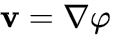

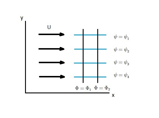
 In the above case we have a flow entering a pipe in the top-left corner, and exiting in the bottom-right. Each green and red line depicts a direction along which the stream and potential functions, respectively, are constant. From this it becomes clear that the stream function models the path particles will take when suspended in and carried by the fluid, while the potential function is an analogous term whose lines of constant potential run perpendicular to the streamlines.